Menu
Search
Personal menu
Products
Menu
Close
- Coming Soon
- New
- Clearance
- On Sale
- Explore Our Brands
-
Residential
- Back
- Audio
- A/V Racks
- Bulk Wire & Connectors
- Cables
- Cellular Signal Booster
- Fibre
- Headphones
- Lighting Control & Shading Solutions
- Media Distribution
- Mounts
- Networking
- Power
- Projectors & Screens
- Residential Automation
- Residential Speakers
- Safety
- Security & Smart Home
- Structured Wiring
- Surveillance
- Televisions
- Tools & Hardware
-
Commercial
- Back
- Audio
- A/V Racks
- Bulk Wire & Connectors
- Cables
- Cellular Signal Booster
- Conferencing
- Connectivity Boxes
- Control
- Digital Signage
- Fibre
- Headphones
- Lighting Control & Shading Solutions
- Media Distribution
- Microphones
- Mounts
- Networking
- Outdoor TVs
- Power
- Projectors & Screens
- Safety
- Speakers
- Structured Wiring
- Surveillance
- Tools & Hardware
- Video Wall/Multi-Viewer
- Wireless Collaboration
- Automotive
- Home Page
- Services
- Company
- Support
- Contact
-
Products
- Back
- Coming Soon
- New
- Clearance
- On Sale
-
Residential
- Back
- Audio
- A/V Racks
- Bulk Wire & Connectors
- Cables
- Cellular Signal Booster
- Fibre
- Headphones
- Lighting Control & Shading Solutions
- Media Distribution
- Mounts
- Networking
- Power
- Projectors & Screens
- Residential Automation
- Residential Speakers
- Safety
- Security & Smart Home
- Structured Wiring
- Surveillance
- Televisions
- Tools & Hardware
-
Commercial
- Back
- Audio
- A/V Racks
- Bulk Wire & Connectors
- Cables
- Cellular Signal Booster
- Conferencing
- Connectivity Boxes
- Control
- Digital Signage
- Fibre
- Headphones
- Lighting Control & Shading Solutions
- Media Distribution
- Microphones
- Mounts
- Networking
- Outdoor TVs
- Power
- Projectors & Screens
- Safety
- Speakers
- Structured Wiring
- Surveillance
- Tools & Hardware
- Video Wall/Multi-Viewer
- Wireless Collaboration
- Automotive
- Explore Our Brands
- Home Page
- Services
- Company
- Support
- Contact
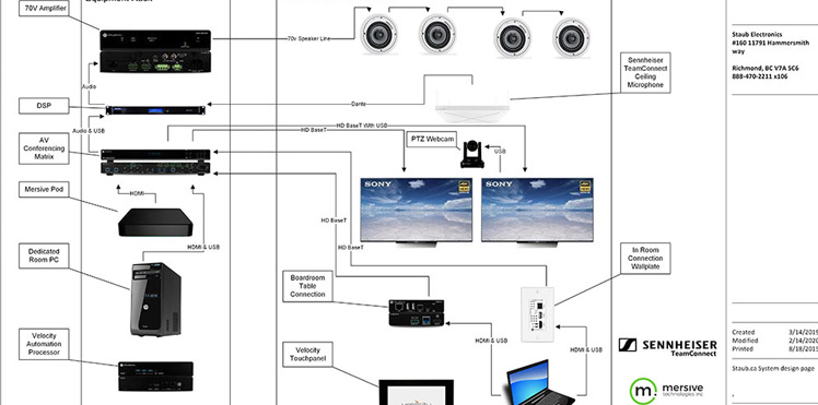
System Design
Staub’s Technical Specialists will work closely with you on your project to ensure a complete and effective Design solution.
RMA Request Form
Simply complete the form and we will process your request or contact you if further information is needed.

Staub Shipping Desk
Tired of paying the posted rates on everything you ship? Tap into our discounts with major shipping carriers to save you money.
Newsletter
Wait...
Information
My Account
Customer service


Copyright © Staub Electronics. All rights reserved.
We bring together the best people, partners, and products to make lives more enjoyable, connected, and secure.
Resources
My Account
Customer Service
Stay Connected
© Copyright Staub Electronics | Privacy Policy | Terms & Conditions